Chemical Equipment Technical Document: Based Relay Design and Application of digital measurement STM
Abstract: Measuring relays with digital measurement precision, simple setting, protection features and more, speed, etc., is the traditional electromagnetic, static relays ideal alternative. This paper describes the overall design of a measure based STM32F103R8T6 digital relays. The product can be protected against multiple failures of different objects encountered in actual use, so that the object to be protected will not cause damage during a fault condition, improve reliability and reduce losses.
Keywords: digital, measuring relays, protection
1.1 host CPU
The relays measure CPU use ST-based company's latest ARM Cortex-M3 32-bit processor core architecture STM32F103R8T6, clock frequencies up to 72MHz, the built-in 64K of Flash, 20K of RAM, 12 位 AD, 4 16-bit timers , 3-way multiple resources USART communication ports, etc., with a very high price.
1.2 Power
Power is a key part of the device can be normal, stable and reliable operation of the relay using the company's popular universal switching power supply module. The power module input voltage is AC85V ~ 265V, input frequency 45Hz ~ 60Hz, with multi-channel isolation voltage output to meet a variety of functions for different supply voltage requirements. Output voltage stability, low failure rate, output ripple <1%. Overvoltage, overcurrent protection. The module is the actual field use, high stability, reliability and performance.
1.3 signal acquisition circuit
Signal acquisition circuit isolation transformer input current and voltage power signal isolation, improve the safety and reliability of the system. After sampling signal amplifier circuit for A / D conversion. figure 2.
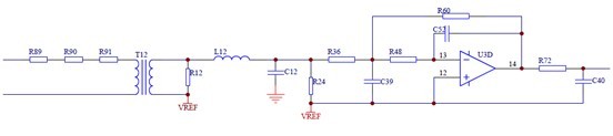
2 signal acquisition circuit diagram
1.4 interactive unit
Interactive unit with LED display and key input, the system uses a single row of four LED digital display a variety of information. The user can be set according to actual needs. Display menus and parameters in the programming mode. Digital display dynamic scanning mode, the drive circuit uses a 74HC595 plus transistor constituted.
1.5 RS485 communication interface
Communication interface module using a common RS-485, Modbus RTU communication protocol, to achieve telemetry, remote control, remote functions, shown in Figure 3.
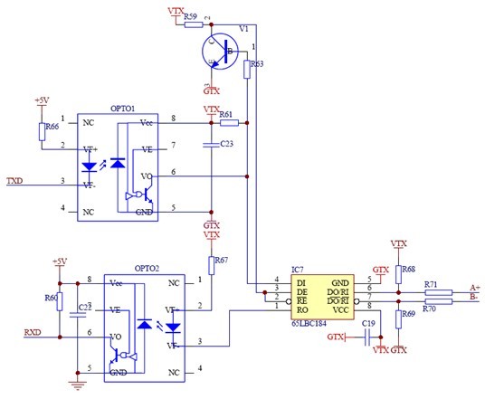
Figure 3 Communication circuit diagram
1.6 Relay Output Interface
Relay output interface (Figure 4) is the executive body movement, when a fault occurs, the relay will generate action, an alarm or a trip signal.
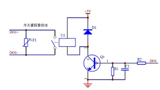
Figure 4 relay outputs Schematic
2 software design
Since the measuring relays with digital circuits, the core element is used in 32-bit microcontroller, operation speed (clock frequency 72MHz), protection algorithms implemented in software, therefore, by the same electrical parameters of the extended protection functions can be integrated out in one ( The measurement of three-phase current can achieve overload, underload, unbalance, phase loss, phase sequence and other protection), unlike the static relays, as different protection functions require different analog circuits to achieve, often only lead to a single static relay a protective function.
2.1 Program Design
Software Design The relay includes computing, protection, display, various functions subroutines buttons, communications and so on. Wherein the calculation routine is mainly used for signal acquisition and computing, real-time measurement of electrical parameters of the protected object; there are various protection subroutines major integrated protection algorithm, various parameters will be measured with a preset value to compare, to determine if there is a failure, timely protection; display, key subroutine for human-computer interaction; communication routines are used to a variety of parameters through the communication interface control system backstage pass away.
Because the program more content, now gives the main program flow (Fig. 5) and the protection subroutine flow chart (Figure 6).
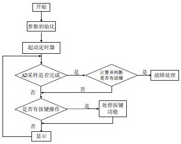
5 The main program flowchart of FIG.
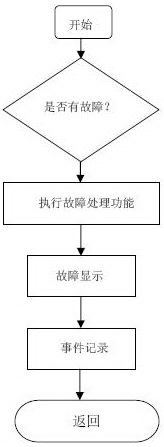
6 protection subroutine flowchart of FIG.
2.2 oversampling
In the product design, targeted at either use it as a protective relay, but also as a low-voltage electrical measuring instruments, thus requiring the measurement accuracy of this product to be high, but due to cost considerations, the use of internal self-master chip STM32F103R8T6 12 AD band, to achieve high-precision measurement, sampling techniques used in the sampling on too. According to the Nyquist theorem can be obtained, for each additional one resolution, the signal must be four times the rate of oversampling: fos = 4w × fs. Wherein, w is desirable to increase the resolution in bits, fs is the sampling frequency of the original claim, fos is the oversampling frequency. According to this formula, the sampling will increase the sampling frequency of 256 times the resolution of the upcoming four-digit increase, reaching a 16-bit resolution. With this method, the measurement accuracy of this product reached 0.5, fully meet the requirements of a measuring instrument type. Because the CPU speed quickly, it will not because the use of over-sampled, the sampling points and increasing the amount of computation and lead to protection fast enough.
3 Performance Testing
3.1 measurement accuracy test (current type)
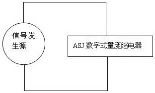
Figure 7
Test device shown in Figure 7, the signal generating source using the company's RTU Shenzhen Clou verification device CL301V2-R, accuracy class 0.05. CL301V2-R output from the three-phase alternating current measurement accuracy ASJ test, the test results shown in Table 1.
Table 1
DK output value
|